The 3D view window opens automatically during PyCAM's startup. You can hide it via the usual close icon of your window manager or by disabling the 3D View Window checkbx in the Windows menu.
The 3D view is based on OpenGL. Thus the respective libraries are recommended. See the list of dependencies for more details. You can use PyCAM even without OpenGL, but the lack of a 3D preview will probably hinder your workflow.
The OpenGL visualization is currently not highly efficient. Maybe you will want to close the window temporarily while working on complex models (eg. some 10k triangles).
Visual features
Model
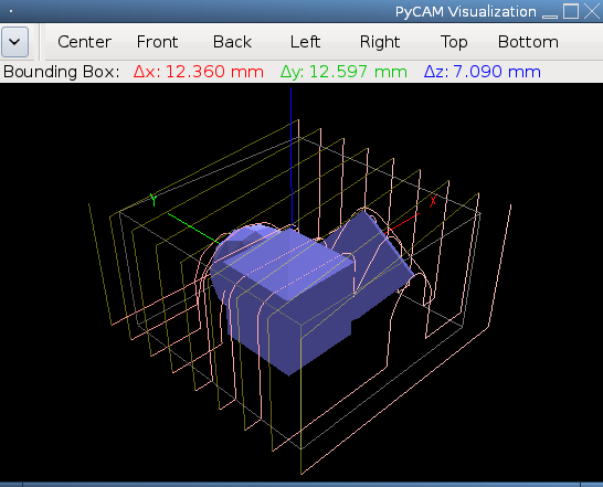
The 2D contour model or the solid 3D model is displayed. See the OpenGL settings below for more configurable details.
Support bridges
Support bridges are only visible if you enabled this feature for your model.
Toolpaths
By default only the most recently generated toolpath is visible. Open the Toolpaths tab if you want to see previous toolpaths.
A toolpath consists of cutting moves and safety moves. The latter are straight vertical moves up to safety height (see GCode preferences) or horizontal moves at safety height. Safety moves are drawn (by default) with a reduced opacity.
Bounding box
The current bounding box is (by default) drawn as grey lines. You can select other bounding boxes in the Bounds tab (directly) or in the Tasks tab (indirectly).
Coordinate system
The three axes of the coordinate system are drawn in red (x), green (y) and blue (z). Hint: just remember RGB.
Dimensions
The size of the current bounding is visible below the toolbar.
Additionally the stretch of the model along the three axes is displayed.
Directions
The following directions can be visualized (optional - see Configuration below):
- toolpath direction
- directions of 2D model contour lines
- the normals of surface triangles (3D models only)
The directions of lines are visualized as cones placed in the middle of each line.
The triangle's normals are shown as short lines starting in the center of each triangle pointing in the normal's direction.
The winding state of each polygon is visualized via its transparency. The outlines of holes are drawn half transparently. “Outside” polygons use full opacity.
Configuration
Visible items
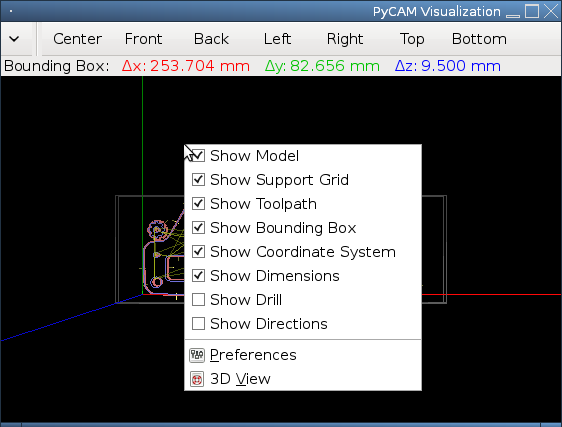
All visible features of the 3D view can be selected in two different locations:
- the Visible items tab in the Preferences window
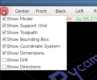
- a drop-down list in the top left corner of the 3D view window (click at the small arrow icon)
- the context menu of the 3D view area (click with the right mouse button)
Colors
The colors of all visible items can be configured in the Colors tab of the Preferences window. Reduce the opacity of specific items (e.g. for toolpath safety moves) to highlight the importance of other items.
OpenGL
There are some OpenGL properties available for configuration:
- Polygon fill: draw solid triangles instead of wireframes (only for 3D models)
- Lighting: enable a directed source of light (instead of homogeneously distributed light
- Shadows: enable the shadow effect (only useful with directed light)
- Perspective View: switch between orthogonal and perspective view mode. The orthogonal view is useful for verifying the alignment of model features, but rotation, zooming and panning don't work perfectly. The perspective view is recommended instead.
Usage
The 3D view can be rotated, zoomed and panned arbitrarily.
The small arrow at the top left corner of the window contains a drop-down list of the currently enabled visualization features.
The 3D view area contains a context menu for visualization features and for the Preferences window.
View templates
The right part of the window's toolbar consists of seven view templates:
- Center: the default angular view
- Front: xz-plane looking at the positive y direction
- Back: xz-plane looking at the negative y direction
- Left: yz-plane looking at the positive x direction
- Right: yz-plane looking at the negative x direction
- Top: xy-plane looking at the negative z direction
- Bottom: xy-plane looking at the positive z direction
Mouse control
Drag the mouse while holding down one of these mouse buttons:
- Left button: rotate the view. The rotation speed increases with the distance from the window's center.
- Right button: zoom the view. Dragging the mouse to the right or up zooms in.
- Middle button: pan the view.
The scroll wheel of your mouse allows the following operations (mimicking Inkscape's behaviour):
- pan upwards: scroll up
- pan downwards: scroll down
- pan right: SHIFT + scroll up
- pan left: SHIFT + scroll down
- zoom in: CTRL + scroll up
- zoom out: CTRL + scroll down
Keyboard control
See the list of shortcuts for the complete reference of keyboard controls.